
| SRS Home | Front Page | Monthly Issue | Index |
|
|
In a recent project I implemented angular feedback using an incremental encoder. The intent of this article is not to rehash a well known concept, but to show the particulars of my implementation. Additionally, I provide the source code to implement the system as this ties directly to the type of feedback required in many robots.
Personal robotics like many other hobbies suffers greatly from monetary constraints. To address this issue, I choose a single chip implementation. Initial designs centered around the issues of resolution lines vs. Frequency and speed of logic required to decode the same. I settled on a lower resolution encoder with a high mechanical input ratio. This again minimized cost as high line count encoders come with a hefty price tag built in as an added feature. One of the key observations made was to implement the mechanical gain ratio (gear pair) through a single linkage to minimize slop and backlash. Additionally, the use of split pre-loaded matched pair gear further helps to reduce errors incurred through the mechanical linkage.
My first thoughts were to develop a custom FPGA to handle the high speed single chip implemenation. Money constraints specifically those involved with the tremendous amount of debug time pointed me back to the PIC processor by MicroChip. Other design considerations focused around the number of pins required to interface to the encoder (2) and the monitoring processor system (8). Still further investigation revealed the need to determine the maximum number of instructions that could be executed between the phase changes of the encoder. With the simple timing cycles presented by the RISC architecture style, this was easily accomplished, by literally counting them up during the preliminary code layout sessions.
Software on the system consists of a state machine which continuously runs at the maximum speed of the processor. (20MHz) Continuous cycling contrast sharply to a solid state system which only cycles when a state change occurs. This cycling was mandated by the need to keep up with the polled communications protocol of the controlling processor. The design called for readings to be taken before the motion, during the motion (both minimum and maximum values), and final resting position. To implement this, the counter runs continuously. The system copies the value of the counter into four separate two byte registers when instructed to do so by the controlling processor. These registers being Zero1 & 2, High1 & 2, Low1 & 2 and Cur1 & 2. An additional design constraint is imposed that the maximum and minimum values can only be recorded once the encoder has passed across the zero reference point. A simple flag (record) is set to 0 upon system reset. The two byte counter is continuously checked in both the increment and decrement routines for the zero condition. Once it has been detected, the record flag is turned on. With the record flag on, the maximum and minimum values are updated as well as the counter.
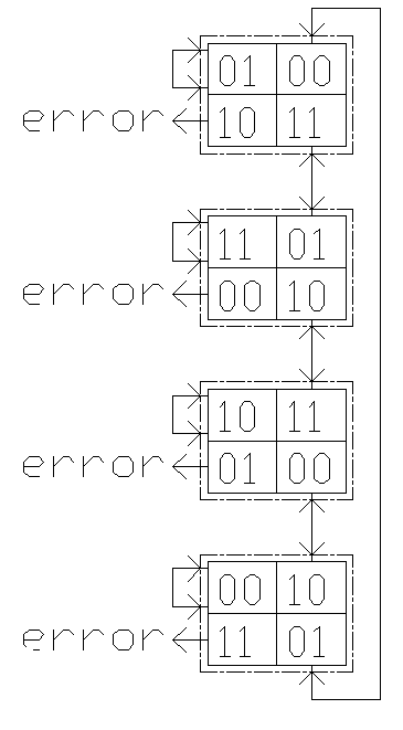 |
State machine
Increment Counter
|
The microcomputer that receives the input from the encoder system, interfaces through an eight bit interface. In the state cycle above, the first step is to check the control byte from the master processor. Control is passed to the PIC processor through port RB0..7. This control byte can tell the system to perform one of the following functions:
During these operations, the state machine continues to operate such that there is never a state loss. Before each data transfer, the controlling microprocessor requests a self test byte, a preset value which is composed of 01010101b. This byte lets the main processor know that the system is operating properly and following this, the request for the appropriate data byte or function may be made. If the self test byte 01010101b is not transmitted by the state system, then main processor system can identify that an error has occurred and can signal the user to perform the measurements over again. Each of the system data transfers is a two byte transfer and there are six transfers to be made. The self test value is checked between each transfer which leads to the chance for error being, conservatively stated, small.
To apply this code to provide feedback from the wheels of your robot real time, all one must do is remove the flag checking on the count up and count down subroutines. They prefilter the counting mechanism to make sure that certain conditions particular to this project had been met. Specifically, these filters make sure that the counter passes back across the zero point before the minimum and maximum functions are enabled. If you have no need for the minimum and maximum function, simply use the code as is, and you will be able to read current counter high and low byte as well as having access to the reset function. Just a note, resetting the system writes 0x8088 to the counter rather than 0x0000.
;----------------------------------------------------
; Foam1.src
;       Pic 16C55 state machine code to de-encode
;       4,000 line incremental two line encoder
;       attached to port A and communicate with
;       8031ah based host through ports B & C
; By:
;       Kenneth Y. Maxon
; On:
;       3/12/97 - 3/18/97
;----------------------------------------------------
        org     8
recflg  ds      1
acc     ds      1
cur1    ds      1                       ; stored low byte of counter var
cur2    ds      1                       ; stored high byte of counter var
zero1   ds      1
zero2   ds      1
high1   ds      1
high2   ds      1
low1    ds      1
low2    ds      1
p1      =       ra                      ; point to port of encoder attachment
p2      =       rc                      ; point to the command port
p3      =       rb
buffer  =       010h                    ; shared data ram
        org     0
        device  pic16c55,hs_osc,wdt_off,protect_off
        reset   begin

begin   mov     !ra,#00001111b          ;define input only low four bits hooked up
        mov     !rb,#0                  ;define output, 0's are outputs
        mov     !rc,#00001111b          ;define some input, 0's are outputs
        mov     recflg,#0
        goto    record
;----------------------------------------
state0  lcall   disptch
        mov     acc,p1
        AND     acc,#00000011b
        cjne    acc,#00000001b,atate1
        goto    state0                  ;rem were here in state 0 and nothing has changed
atate1  cjne    acc,#00000011b,atate2
        lcall   cntup                   ;rem were here in state 0 and we're going to state #1
        goto    state1
atate2  cjne    acc,#00000000b,atate3
        lcall   cntdwn                  ;rem were here in state 0 and we're going to state #3
        goto    state3
atate3  mov     p3,#11h
        goto    atate3                  ;were here because a state error has occured
;----------------------------------------
state1  lcall   disptch
        mov     acc,p1
        AND     acc,#00000011b
        cjne    acc,#00000011b,btate1
        goto    state1                  ;rem were here in state 1 and nothing has changed
btate1  cjne    acc,#00000010b,btate2
        lcall   cntup                   ;rem were here in state 1 and we're going up to state #2
        goto    state2
btate2  cjne    acc,#00000001b,atate3
        lcall   cntdwn                  ;rem were here in state1 and we're going down to state #0
        goto    state0
btate3  mov     p3,#011h
        goto    btate3                  ; were here because a state error has occured

;----------------------------------------
state2  lcall   disptch
        mov     acc,p1
        AND     acc,#00000011b
        cjne    acc,#00000010b,ctate1
        goto    state2                  ;rem were here in state 2 and nothing has changed
ctate1  cjne    acc,#00000000b,ctate2
        lcall   cntup                   ;rem were here in state 2 and we're going up to state #3
        goto    state3
ctate2  cjne    acc,#00000011b,ctate3
        lcall   cntdwn                  ;rem were here in state 2 and we're going down to state #1
        goto    state1
ctate3  mov     p3,#011h
        goto    ctate3                  ;were here because some sort of state error has occured
;----------------------------------------
state3  lcall   disptch
        mov     acc,p1
        AND     acc,#00000011b
        cjne    acc,#00000000b,dtate1
        goto    state3                  ;rem were here in state 3 and nothing has changed
dtate1  cjne    acc,#00000001b,dtate2
        lcall   cntup                   ;rem were here in state 3 and we're going up to state #0
        goto    state0
dtate2  cjne    acc,#00000010b,dtate3
        lcall   cntdwn
        goto    state2                  ;rem were here in state 3 and we're going down to state #2
dtate3  mov     p3,#011h
        goto    dtate3                  ;were here because an error has occured
;----------------------------------------
;come here to increment the current count
;----------------------------------------
cntup   setb    p2.6
        clrb    p2.6
        clc
        add     cur1,#01h
        addb    cur2,c                  ;add bit to fr (btfsc fr,b incf fr,1)
        cjne    recflg,#00,ctupyep      ;check to see if we're recording

        cjne    cur1,zero1,ctdnnada     ;turn it on?
        cjne    cur2,zero2,ctdnnada
        mov     acc,p2                  ;will the 8031 let us record yet
        and     acc,#00001111b
        cjne    acc,#00000001b,ctdnnada
        mov     recflg,#01h

ctupnada setb   p2.7
        nop
        nop
        nop
        clrb    p2.7
        ret                            ;record flag cannot come on in count up mode
;----------------------------------------
;okay here were recording, so check the max values
;if cur2 > high2 then update
;if cur2 < high2 then return
;fall through if cur2 = high2
;if cur1 > hgih1 then update
;return
;----------------------------------------
ctupyep setb    p2.7
        clrb    p2.7
        cja     high2,cur2,ctupdt       ;first is above second ?
        cjb     high2,cur2,ctupdn       ;first is below second ?
        cja     high1,cur1,ctupdt       ;first is above second ?
        setb    p2.6
        nop
        clrb    p2.6
ctupdn  ret                             ;count_up_done
ctupdt  mov     high1,cur1              ;count_up_update
        mov     high2,cur2
        setb    p2.7
        nop
        clrb    p2.7
        ret
;----------------------------------------
;come here to decrement the current count
;----------------------------------------
cntdwn  setb    p2.6
        clrb    p2.6
        clc
        sub     cur1,#01h
        subb    cur2,c
        cjne    recflg,#00,ctdnyep      ;check to see it we're recording
        cjne    cur1,zero1,ctdnnada     ;turn it on?
        cjne    cur2,zero2,ctdnnada
        mov     acc,p2                  ;will the 8031 let us record yet
        and     acc,#00001111b
        cjne    acc,#00000001b,ctdnnada
        mov     recflg,#01h

ctdnnada setb   p2.7
        nop
        nop
        nop
        clrb    p2.7
        ret
;----------------------------------------
;okay were recording, so check the min values
;if cur2 < low2 then update
;if cur2 > low2 then return
;fall through if cur2 = high2
;if cur1 < low1 then update
;else return
;----------------------------------------
ctdnyep setb    p2.7
        clrb    p2.7
        cjb     low2,cur2,ctdndt        ;second below?
        cja     low2,cur2,ctdndn        ;second above?
        cjb     low1,cur1,ctdndt        ;second below?
        setb    p2.6
        nop
        clrb    p2.6
ctdndn  ret                             ;count_down_done
ctdndt  mov     low1,cur1               ;count_down_update
        mov     low2,cur2
        setb    p2.7
        nop
        clrb    p2.7
        ret
;----------------------------------------
;main dispatch table
disptch mov     acc,p2
        and     acc,#00001111b
        cjne    acc,#00000000b,disp2
        goto    cntrst
disp2   cjne    acc,#00000001b,disp3
        ret
disp3   cjne    acc,#00000010b,disp4
        goto    outhigh
disp4   cjne    acc,#00000011b,disp5
        goto    outhigl
disp5   cjne    acc,#00000100b,disp6
        goto    outlowh
disp6   cjne    acc,#00000101b,disp7
        goto    outlowl
disp7   cjne    acc,#00000110b,disp8
        goto    outzerh
disp8   cjne    acc,#00000111b,disp9
        goto    outzerl
disp9   cjne    acc,#00001000b,disp10
        goto    outcurh
disp10  cjne    acc,#00001001b,disp11
        goto    outcurl
disp11  cjne    acc,#00001111b,disp12
        goto    pmode
disp12  ret

;----------------------------------------
;the record routine begins with find state
record  mov     acc,p1
        AND     acc,#00000011b
        cjne    acc,#00000000b,fstate1
        goto    state3
fstate1 cjne    acc,#00000001b,fstate2
        goto    state0
fstate2 cjne    acc,#00000010b,fstate3
        goto    state2
fstate3 goto    state1
;----------------------------------------
;this routine zeros out the counters
cntrst  mov     zero1,#88h                 ;arbitrarily choosen zero value fill
        mov     zero2,#80h                 ;in with appropriate values later...
        mov     cur1,#88h
        mov     cur2,#80h
        mov     high1,#88h
        mov     high2,#80h
        mov     low1,#88h
        mov     low2,#80h
        mov     recflg,#0               ;turn of the record function
        ret
;----------------------------------------
outhigh mov     p3,high2
        ret
outhigl mov     p3,high1
        ret
;----------------------------------------
outlowh mov     p3,low2
        ret
outlowl mov     p3,low1
        ret
;----------------------------------------
outzerh mov     p3,zero2
        ret
outzerl mov     p3,zero1
        ret
;----------------------------------------
outcurh mov     p3,cur2
        ret
outcurl mov     p3,cur1
        ret
;----------------------------------------
pmode   mov     p3,#01010101b
        ret
Since building the original measuring apparatus two months ago, I've used this code in three separate projects with only minor code modifications. I hope that this code can help you in your next robotics project.